jueves, 26 de noviembre de 2015

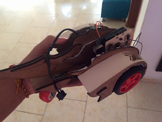
PROYECTO FINAL-SEGUIDOR DE LINEA "BOLD"

Descripción:

Realizamos un carro seguidor de linea el cual todo sus componentes electrónicos son controlados por la tarjeta arduino(UNO), este carro consta de dos sensores CNY70, dos motor reductores los cuales son controlados por el circuito integrado L293D y tambien le agregamos dos LEDs tricolor(estética).

Materiales: 
 
  • Arduino UNO con su respectivo cable USB
  • Computador con el respectivo software de arduino
  • 2 motores reductores
  • 2 sensores CNY70
  • Diodos 1n4007 de proteccion
  • Resistencias 330 y 1k
  • Integrado L293D
  • Chasis de material MDF
  • Carton paja
  • Rueda loca
  • Cables
Diagrama:

Montaje


PCB

(Vaquela)


Código

  1. // Proyecto Final
  2. // Programa Arduino
  3. // Seguidor de linea
  4. // Johnson Camilo Barona Sanchez
  5. // Programacion de sistemas embebidos
  6. // Universidad Santiago de Cali
  7.  
  8. // inicio de código
  9. // Declaramos las constantes  
  10.  
  11. const int pinSensorA = 0;
  12. const int pinSensorB = 1;
  13. const int pinMotorA = 5;
  14. const int pinMotorB = 6;
  15. const int pinMotorC = 9;
  16. const int pinMotorD = 10 ;
  17.  
  18. // Declaramos las variables
  19.  
  20. int ValorSensorA;
  21. int ValorSensorB;
  22.  
  23. // Declaracion de constantes como salidas
  24.  
  25. void setup() {
  26.   pinMode(pinMotorA,OUTPUT);
  27.   pinMode(pinMotorB,OUTPUT);
  28.   pinMode(pinMotorC,OUTPUT);
  29.   pinMode(pinMotorD,OUTPUT);
  30.  
  31. // Inicia los motores apagados
  32.  
  33.   digitalWrite(pinMotorA, LOW);
  34.   digitalWrite(pinMotorB, LOW);
  35.   digitalWrite(pinMotorC, LOW);
  36.   digitalWrite(pinMotorD, LOW);
  37.  
  38. }
  39.  
  40. void loop() {
  41.   //Asigna lectura analoga de los sensores a las variables valor sensor A y sensor B B
  42.  
  43.   ValorSensorA = analogRead(pinSensorA);
  44.   ValorSensorB = analogRead(pinSensorB);
  45.  
  46. // condicion para el sensor A
  47.  
  48.   if(ValorSensorA <= 10)
  49.   {
  50.      digitalWrite(pinMotorA, LOW);
  51.      digitalWrite(pinMotorB, HIGH);
  52.   }
  53.   else {
  54.     digitalWrite(pinMotorA, HIGH);
  55.      digitalWrite(pinMotorB, LOW);
  56.   }
  57.  
  58.   // condicion para el sensor B
  59.  
  60.   if(ValorSensorB <= 110)
  61.   {
  62.      digitalWrite(pinMotorC, LOW);
  63.      digitalWrite(pinMotorD, HIGH);
  64.   }
  65.   else {
  66.     digitalWrite(pinMotorC, HIGH);
  67.      digitalWrite(pinMotorD, LOW);
  68.   }
  69.   }


Proceso de Montaje

Integrado

Motores reductores 


Senosr CNY70


Vídeo corte de algunas piezas


Después de cortado nuestro chasis procedemos a ensamblar las piezas y componentes electrónicos. 


Vídeo Funcionamiento


miércoles, 11 de noviembre de 2015

Laboratorio # 11

Descripción:

Este laboratorio consiste en mostrar un mensaje a través de una matriz de LEDs 8x8 ,en donde esta matriz recibirá los datos en modo serial por parte de un IC MAX7219 que controlara la visualización del byte enviado. Utilizamos la librería "LedControl.h", la cual es una librería de arduino para controlar el integrado, por medio de esta enviamos los comandos al IC y en el momento poderlos ver en la matriz.

Materiales :


  • Computador con el respectivo software de arduino y processing
  • Arduino con su respectivo cable USB
  • Protoboard
  • Matriz LEDs 8x8 entrada serial desde Interface Max7219
  • Cables

Diagramas :

Montaje


Esquemático


Código

Arduino


  1. // Laboratorio #11
  2. // Programa Arduino
  3. // Controlar una Matriz de leds 8x8 desde una interfaz en Processing
  4. // Johnson Camilo Barona Sanchez
  5. // Programacion de sistemas embebidos
  6. // Universidad Santiago de Cali
  7. // inicio de código
  8. //incluimos la libreria
  9. #include "LedControl.h"
  10. String texto="";
  11. /*
  12.  Now we need a LedControl to work with.
  13.  ***** These pin numbers will probably not work with your hardware *****
  14.  pin 12 is connected to the DataIn
  15.  pin 11 is connected to the CLK
  16.  pin 10 is connected to LOAD
  17.  We have only a single MAX72XX.
  18.  */
  19. LedControl lc=LedControl(12,11,10,1);
  20. /* we always wait a bit between updates of the display */
  21. unsigned long delaytime=40;
  22. void setup() {
  23.   Serial.begin(9600);
  24.   /*
  25.    The MAX72XX is in power-saving mode on startup,
  26.    we have to do a wakeup call
  27.    */
  28.   lc.shutdown(0,false);
  29.   /* Set the brightness to a medium values */
  30.   lc.setIntensity(0,8);
  31.   /* and clear the display */
  32.   lc.clearDisplay(0);
  33. }
  34. char abcMAY[36]={'A', 'B', 'C', 'D', 'E', 'F', 'G', 'H', 'I', 'J', 'K', 'L', 'M', 'N', 'O', 'P', 'Q', 'R', 'S', 'T', 'U', 'V', 'W', 'X', 'Y','Z','1','2', '3', '4', '5', '6', '7', '8', '9', '0'};
  35. char abcMIN[36]={'a', 'b', 'c', 'd', 'e', 'f', 'g', 'h', 'i', 'j', 'k', 'l', 'm', 'n', 'o', 'p', 'q', 'r', 's', 't', 'u', 'v', 'w', 'x', 'y','z','1','2', '3', '4', '5', '6', '7', '8', '9', '0'};
  36. byte letras[36][5]= {
  37.   {B11111110,B00010001,B00010001,B00010001,B11111110},//A
  38.   {0xFF, 0x89, 0x89, 0x89, 0x76},//B
  39.   {B01111110,B10000001,B10000001,B10000001,B01000110},//C
  40.   {0xff, 0x81, 0x81, 0x81, 0x7e},//D
  41.   {0x7e, 0x89, 0x89, 0x89, 0x89},//E
  42.   {0xff, 0x09, 0x09, 0x09, 0x01},//F
  43.   {0x7e, 0x89, 0x89, 0x89, 0xf2},//G
  44.   {0xFF, 0x18, 0x18, 0x18,0xff},//H
  45.   {B00000000,B10000100,B11111101,B10000000,B00000000},//I
  46.   {0x71, 0x81, 0x7f, 0x01, 0x01},//J
  47.   {0xff, 0x10, 0x2c, 0x42, 0x81},//K
  48.   {0x7f, 0xc0, 0x80,0x80, 0x80},//L
  49.   {0xff, 0x06, 0x0c, 0x06, 0xff},//M
  50.   {B11111111,B00000100,B00001000,B00010000,B11111111}, //N
  51.   {B01111110,B10000001,B10000001,B10000001,B01111110},//O
  52.   {0xff, 0x09, 0x09, 0x09, 0x06},//P
  53.   {0xbe, 0x41,0xA1, 0x81, 0x7e},//Q
  54.   {B11111111,B00010001,B00110001,B01010001,B10001110},//R
  55.   {0x86, 0x89, 0x89, 0x89, 0x71},//S
  56.   {0x01, 0x01, 0xff, 0x01, 0x01},//T
  57.   {B01111111,B11000000,B11000000,B11000000,B01111111},//U
  58.   {0x3f, 0x40, 0x80, 0x40, 0x3f},//V
  59.   {0x7f, 0x80, 0x70, 0x80, 0x7f},//W
  60.   {0xe3, 0x14, 0x08, 0x14, 0xe3},//X
  61.   {0x03, 0x04, 0xf8, 0x04, 0x03},//Y
  62.   {0xe1, 0x91, 0x89, 0x85, 0x83 }//Z
  63.   ,{0x00, 0x82, 0xff, 0x80,0x00},//1
  64.   {0xc2, 0xa1, 0x91, 0x89, 0x86},//2
  65.   {0x81,0x81,0x85,0x8b,0x71},//3
  66.   {0x18,0x14, 0x12, 0xff, 0x00},//4
  67.   {0x8f, 0x89, 0x89, 0x89, 0x71},//5
  68.   {0x7c, 0x8a, 0x89, 0x89, 0x70},//6
  69.   {0x01, 0xf1, 0x09,0x05, 0x03},//7
  70.   {0x76, 0x89, 0x89, 0x89, 0x76},//8
  71.   {0x06, 0x89, 0x89, 0x89, 0x7e },//9
  72.   {B01111110,B11100001,B10011001,B10000111,B01111110},//O
  73. };
  74. /*
  75.  This method will display the characters for the
  76.  word "Arduino" one after the other on the matrix.
  77.  (you need at least 5x7 leds to see the whole chars)
  78.  */
  79. void writeArduinoOnMatrix(String mensajea) {
  80.   /* here is the data for the characters */
  81.  for(int j=0;j<mensajea.length();j++){
  82.    for(int k=0;k<36;k++){
  83.  if(mensajea.charAt(j)==abcMAY[k] || mensajea.charAt(j)==abcMIN[k]){
  84.  palabras(letras[k]);
  85.  }
  86.  }
  87.  }
  88. }
  89. void palabras(byte listd[]){
  90.   for(int j=7;j>-4;j--){
  91.    
  92.   for(int i=4; i> -1; i--){
  93.   lc.setRow(0,j+i,listd[i]);
  94.   }
  95.   delay(delaytime);
  96.   for(int o=0; o<8 ; o++){
  97.   lc.setRow(0,o,0);
  98.   }
  99.   }
  100. }
  101. void loop() {
  102.   writeArduinoOnMatrix(texto);
  103. }
  104. void serialEvent(){
  105. while(Serial.available()){
  106. texto= Serial.readString();
  107. }
  108. }


Processing

  1. // Laboratorio #11
  2. // Programa Arduino
  3. // Controlar una Matriz de leds 8x8 desde una interfaz en Processing
  4. // Johnson Camilo Barona Sanchez
  5. // Programacion de sistemas embebidos
  6. // Universidad Santiago de Cali
  7. // inicio de código
  8. //se carga la libreria ControlP5
  9. import controlP5.*;
  10. //se carga la libreria Serial
  11. import processing.serial.*;
  12. // definir la variable cp5 del tipo ControlP5
  13. ControlP5 cp5;
  14. // definir la variable puerto del tipo Serial
  15. Serial puerto;
  16. // definir la variable text del tipo Textfield
  17. Textfield text;
  18. void setup(){
  19.   //tamaño de la ventana
  20.    size(500,360);
  21.    cp5 = new ControlP5(this);
  22.    text = cp5.addTextfield("Texto")
  23.              .setPosition(30,50)
  24.              .setSize(300,50)
  25.              .setFont(createFont("Arial",30))
  26.              .setAutoClear(false);
  27.           cp5.addButton("Mostrar")
  28.               .setValue(1)
  29.               .setPosition(60,130)
  30.               .setSize(40,30)
  31.               .setId(2);
  32.            
  33.    String COM = Serial.list()[0];
  34.    //comunicacion serial a 9600bps
  35.    puerto = new Serial(this, COM, 9600);
  36. }
  37. void draw(){
  38.    background(#000000);
  39. }
  40. void controlEvent(ControlEvent theEvent){  
  41.   if(theEvent.isAssignableFrom(Button.class)){  
  42.     for(int i = 0; i < text.getText().length(); i++){  
  43.        char dato = text.getText().charAt(i);    
  44.        puerto.write(dato);      
  45.     }
  46.   }
  47. }


Proceso de montaje


Vídeo